In collaboration with the Clinical Skills Team, the Digital Education Unit at the Royal (Dick) School of Veterinary Studies at the University of Edinburgh have developed a Doppler flow measurement simulator to teach the measurement of systolic blood pressure.
Idea and testing by Rob Ward and Caroline Mosley, construction and coding by Eoghan Clarkson.

This work is licensed under a Creative Commons Attribution-NonCommercial-ShareAlike 4.0 International License.
The idea
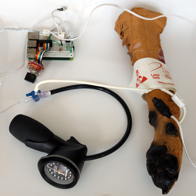
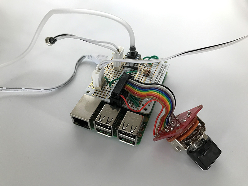
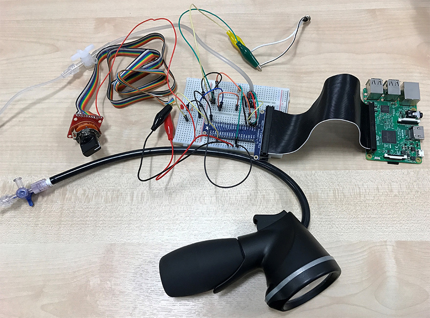
Doppler flow measurement is a cheap technique for non-invasive measurement of systolic blood pressure commonly used in small animal practices, and as such is a skill we require our students to master. The technique can be practised on live animals or students themselves, but at Edinburgh we are reducing our use of live animals and have safety concerns about self-experimentation. Also, practising on a live subject does not produce consistent and repeatable results that can be later checked for accuracy. As a result of collaboration between our Clinical Skills Team and Digital Education Unit, we created a prototype Doppler flow measurement simulator using a Raspberry Pi and Arduino together (low-cost computers, about the size of a credit card, which can be extended by adding environmental sensors). This prototype was later refined to require only the Raspberry Pi, and both versions have since been used by students during Clinical Skills practicals.
The plan
Rob and Caroline’s idea was to use a Raspberry Pi to simulate Doppler flow measurement in small animals.
- A ‘Doppler probe’ would be placed on a dummy of a canine forelimb.
- When in the correct position to take measurements, the sound of blood flowing forward and back would be played through a speaker.
- The student would inflate a cuff using a sphygmomanometer, until the blood flow sound stops.
- They then deflate the cuff until they hear the sound of blood flowing forward, but not back, and note the systolic blood pressure.
- They continue to deflate the cuff until they hear the sound of blood flowing forward and back again, and note the diastolic blood pressure.
The original idea was that one blood pressure reading would be programmed into the Raspberry Pi.
Optional extension
A further idea we had was that a rotary switch could be added, which would allow students to select a number of different blood pressures to try measuring.
NOTE: As an emergency measure, if the probe doesn’t seem to work and the blood pressure can’t be heard when placing it, then setting the rotary switch to position ’10’ will ignore the need to place the probe in the correct position, and will cause the blood pressure sound to be heard regardless.
The parts
Standard electronic parts:
- Raspberry Pi – £34.07
- Power supply – £7.80
- 16GB microSD Card – £12.88
- Digital Pressure Sensor (HONEYWELL SSCDANN015PG2A3) – £26.53
- Reed Switch – £8.75 (you can get cheaper reed switches, but they can break more easily)
- Small magnet – £0.77
- 2 core wire, 1m – £0.36
- USB Speakers: We used Betron Pop Up Portable Travel Speaker – £25 (you can get a few of these and chain them together – but other speakers might be louder)
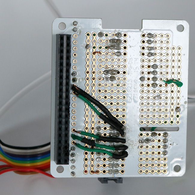
- Perma-Proto HAT (No EEPROM) – £6.18
- Mini push-button momentary switch – £3.18
- Resistors (2 x 1kOhm)
- A small copper stripboard to cut up – £6.32
- Heat shrinkable sleeving, large enough diameter to enclose the probe.
Specialised parts:
- Canine Foreleg model (this can be made yourself, or we used one of UC Davis’s Canine Foreleg Models)
- Sphygmomanometer (optionally with cuff)
Optional parts
Parts to allow probe and shutdown button to be detached an other ones attached:
- 2 x IDC Connector Socket, 2 Way, 1 Row – £1.90 for 10
- 2 x Straight PCB Header, 2 Way, 1 Row – £1 each
Rotary switch, to allow different pressure values to be selected:
- Rotary Switch – £2.29
- Rotary Switch Breakout – £2.29
- Black Knob – £1.00
- Ribbon cable (ideally at least 11pin for 10-way rotary switch) – £3.19
And the following are useful if you want to be able to attach and detach the rotary switch:
Pressure sensor
We used a HONEYWELL SSCDANN015PG2A3 digital pressure sensor, and the code and wiring diagram are designed for this sensor.
If another sensor is used, then the code for reading the sensor in file pressure_sensor.py would need to changed, specifically the functions:
- read_pressure_sensor_count() which gets a reading from the sensor.
- read_pressure_sensor_psi() which uses the pressure formula in the sensor’s technical datasheet to convert the reading to PSI.
Maxiumum pressure
Different sensors will have different ‘over-pressure’ ratings.
The Honeywell sensor we used has an ‘over-pressure’ rating of 30 psi (1551 mmHg) – which is “The maximum pressure which may safely be applied to the product for it to remain in specification once pressure is returned to the operating pressure range. Exposure to higher pressures may cause permanent damage to the product.”
Setting up the Raspberry Pi
- See my Set Up Raspberry Pi instructions for basic set up instructions, including connecting to eduroam WiFi.
- This project uses the I2C port, which isn’t enabled by default. To enable it from the command line:
- Start the config menu, with:
sudo raspi-config
- Use your keyboard’s down-arrow to highlight ‘Interfacing Options’, and select it by pressing the Return key.
- Use the down-arrow key and return to select ‘I2C’.
- Use the left-arrow key to select ‘Yes’ and press Return.
- A message will say I2C has been enabled, press Return to select ‘Ok’
- Press the right-arrow key to select ‘Finish’ and press Return.
- Start the config menu, with:
The Python code
I used Python 3, which is available on the Noobs install. The code is available on my GitHub blood_pressure project.
Before downloading the code, make sure your Raspberry Pi OS is up-to-date, by running:
sudo apt update
sudo apt full-upgrade
The following steps create the directory, and download the code into it from GitHub:
- Set up a directory on your Pi for the project – in ‘Documents’, I usually create a ‘Python Projects’ directory, then a directory for the project:
mkdir ~/Documents/Python\ Projects
cd ~/Documents/Python\ Projects
- Download the source code for this project:
git clone https://github.com/eoghan-c/blood_pressure.git
- When the download is complete, you should be able to open the new ‘blood_pressure’ directory, and see the downloaded files inside:
cd blood_pressure
ls -la
The master script which runs the project is main.py and once you have finished hooking up the hardware.
- You can run the program using:
sudo python3 main.py
- And exit the program by pressing Ctrl-C on the keyboard.
The ‘Auto-run the script on boot‘ section near the end of these instructions shows you how you can make the script launch automatically when the Pi boots up, so it can be run without a keyboard or monitor (and the ‘Shutting down‘ section below it explains how you can quit the program, or shutdown the Pi without a keyboard).
Hardware
Variables in the code
The variables defined for the hardware in config.py are:
| Variable | Description |
|---|---|
| animals_dir | The name of the main sounds directory. Inside this are directories for each group of sounds |
| probe_not_in_position_filename | The filename of the .WAV sound to play when the probe is not in the correct position |
| normal_filename | The filename of the .WAV sound to play when blood is flowing forward and back |
| diastolic_filename | The filename of the .WAV sound to play when the pressure has passed the diastolic point (only forward blood flow) |
| systolic_filename | The filename of the .WAV sound to play when the pressure has passed the systolic point (no sound) |
| stop_button_pin | Push button used to shut down the Pi, see ‘Shutting down’ section below |
| doppler_probe_pin | One side of the reed switch ‘probe’ |
| animal_selector_pins | A list of pins the rotary switch is connected to |
Wiring
For pin numbers of the HONEYWELL SSCDANN015PG2A3 pressure sensor, see ‘DIP AN: Single axial barbed port’ of Fig 4 in its Technical Datasheet. (Note in this project I used GPIO.BCM so the ‘GPIO PIN’ column refers to the BCM numbers)
| Part | GPIO Pin |
|---|---|
| HONEYWELL SSCDANN015PG2A3, Pin 1 | GND |
| HONEYWELL SSCDANN015PG2A3, Pin 2 | 3v3 |
| HONEYWELL SSCDANN015PG2A3, Pin 3 | SDA1 |
| HONEYWELL SSCDANN015PG2A3, Pin 4 | SCL1 |
| One side of ‘doppler_probe_pin’ reed switch. | GPIO 23 |
| Other side of reed switch. | GND |
| Push button ‘stop_button_pin’. | GPIO 22 |
| Other side of push button. | GND |
Fritzing diagram

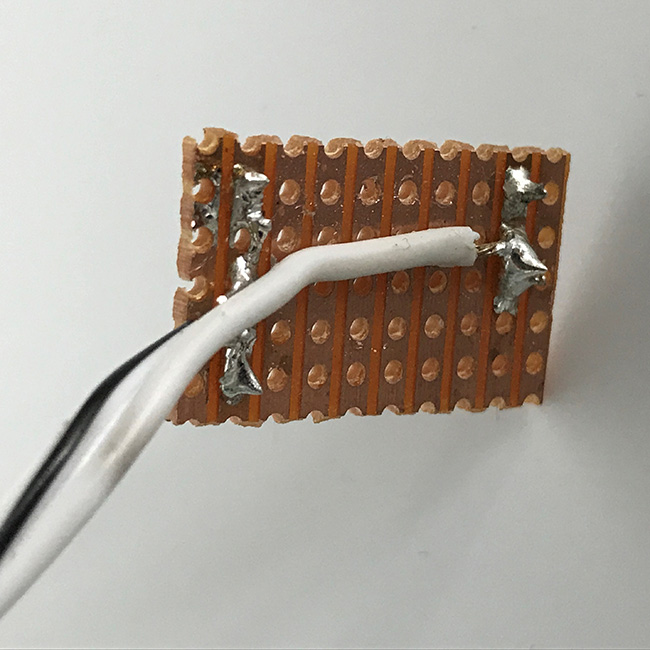
Mounting the optional 2×8 PCB header plug
If you want to attach the 2×8 PCB header plug on the Perma-Proto HAT, I couldn’t find a place for it that would keep it’s pins separate, so we cut through eight copper rails on the HAT using a scalpel.

The probe
For this prototype we decided to use a simple reed switch attached to the end of a 2-core wire for the probe.
I cut a small section of the copper stripboard, enough to mount the reed switch and solder on one end of the 2-core wire:
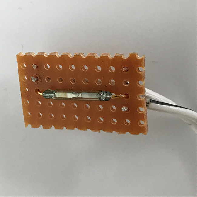
I then covered the stripboard in heat shrinkable sleeving.
The probe trigger
We embedded a small magnet into the model forelimb at the point where the probe should be held to hear the Doppler sounds. We rolled the skin down, cut a small hole, and glued the magnet into it, covering with a thin layer of silicon so it’s not easy to feel the magnet after the skin was replaced.
Setting pressure values
The pressure values are set in the config.py file, in the ‘animals’ variable:
animals = {
              1: ['Cat, normal',   100, 80, 'rob_human_normal'],
              2: ['Cat, abnormal', 130, 90, 'rob_human_normal']
          }
If a rotary switch is added, then multiple pressure values can be added to the ‘animals’ list, as in the code above. If a rotary switch isn’t used, then only pressure value ‘1’ in the list will be used.
The contents of the ‘animals’ list are:
| Human-readable label | systolic pressure | diastolic pressure | name of directory inside ‘sounds’ dir that contains the sound files |
Auto-run the script on boot
I used systemd, as detailed by Matt in How To Autorun A Python Script On Boot Using systemd
(though ‘Type=simple’ seemed to work for my script).
I’ve included the Unit file with the program files, and you can use it if you have installed the scripts into the directory I used):
- Copy the Unit file into the correct location by using:
sudo cp "/home/pi/Documents/Python Projects/blood_pressure/blood_pressure.service" /lib/systemd/system/
- Then refresh the daemon with
sudo systemctl daemon-reload
- And tell systemd to start the service during the boot sequence, with:
sudo systemctl enable blood_pressure.service
- Reboot the Pi:
sudo shutdown -r
- And after rebooting, the Pi should automatically launch the blood_pressure scripts.
The following commands are useful to get the status, or stop the service:
sudo systemctl status blood_pressure.service
sudo systemctl stop blood_pressure.service
The above should create a Unit file at /lib/systemd/system/blood_pressure.service containing:
[Unit]
Description=A Doppler probe simulator for practice measuring blood pressure
After=multi-user.target

[Service]
Type=simple
ExecStart=/usr/bin/python3 "/home/pi/Documents/Python Projects/blood_pressure/main.py"
Restart=on-abort
User=root

[Install]
WantedBy=multi-user.target
Shutting down
As this simulator is designed to run headless, we added a push button to shutdown the Raspberry Pi (connected to pin ‘stop_button_pin’, GPIO 22).
Press the button once to shutdown; press and hold the button for over three seconds to exit the program, but keep the Pi running.
Initially I wanted to add an LED to indicate when the Raspberry Pi was running. After pressing the shutdown button, the Raspberry Pi would be safe to unplug when the LED went out.
Unfortunately there doesn’t seem a simple way to add this sort of power LED (the red LED onboard the Pi stays lit after shutdown, while the power is connected).
In the end we went with the onboard green LED which flashes ten times before shutdown.
So to shutdown – press the button, wait for the green LED to flash ten times, then unplug the Pi.
Troubleshooting
If the program isn’t working as it should, the first thing would be to connect the Pi up to a monitor and keyboard, and boot it up.
In the command line interface, make sure the program isn’t running:
sudo systemctl stop blood_pressure.service
Navigate into the folder containing the program:
g commands are useful to get the status, or stop the service, and manually run the program:
cd ~/Documents/Python\ Projects/blood_pressure
sudo python3 main.py
Hopefully the debug code will give you a clue what’s going wrong.
‘Stop’ button issues
One issue that we have noticed with a Raspberry Pi 4 was that the program thought the ‘stop’ button was always being pressed. We think the issue was solved by making sure the Raspberry Pi operating system was up-to-date, by running:
sudo apt update
sudo apt full-upgrade
Continuous blood pressure sounds
If you have wired a rotary switch to your model, then position ’10’ on the rotary switch is an ’emergency’ setting for cases where the blood pressure sounds can’t be heard even when the probe is placed in the correct position.
If the probe seems to be broken then, until you have a chance to investigate it further, you can move the rotary switch to postion ’10’ and the model will ignore the probe placement and play the blood pressure sounds regardless.
[Errno 121] remote I/O error
We have had reports on newer Raspberry Pi models that the program throws an ‘[Errno 121] remote I/O error’.
It seems this error happens when the program tries to poll the pressure sensor too quickly, and the error can be fixed by slightly increasing the time.sleep() value in the read_pressure_sensor_count() function in the pressure_sensor.py file.
Orignally a delay of time.sleep(0.01) worked well, but if you get ‘[Errno 121] remote I/O error’ errors, try increasing it slightly.
Improvements
Further work to do for this simulator includes:
- Finding a box to put the Raspberry Pi in, and mount the rotary switch.
Further information
For further information, contact Eoghan.Clarkson@ed.ac.uk

hello I really like this, and would love this for my students. is there a way we could purchase one from you?
Hi David, glad to hear this could be useful for you, and thanks for getting in touch.
Up until now, groups in other vet schools have built their own models, but I’ll see whether we would have time to build a model, and how much that would cost us.
One problem might be getting hold of a new canine forelimb model, as UC Davis don’t seem to be selling the model we used anymore.
But I’ll have a chat to people here, and be in touch soon.
Best wishes, Eoghan
This is fantastic! Thank you for sharing your brilliant project!
Thanks Tatiana, I hope it’s helpful!
Thank you for sharing this post
Thanks Bayu, I hope it’s useful!